Anesthesia Breathing Systems
M Ravi Shankar MD and Bhavani Shankar Kodali MD
M Ravi Shankar MD, Formerly Professor and Chair of Anesthesia, JIPMER, India, and presently Presently Professor and Chair of Anesthesiology, Mahatma Gandhi Medical College and Research Institute
Pondicherry, India
For a comprehensive understanding of ‘Anesthesia breathing circuits,‘ click here for a review. It opens a new window. Close the window to return to this section again.
The following section contains pertinent features of anesthesia circuits and their functional analysis for easy understanding facilitated by animations.
DEFINITION
A breathing system is defined as an assembly of components that connects the patient’s airway to the anesthetic machine creating an artificial atmosphere from and into which the patient breathes
It primarily consists of
a) A fresh gas entry port/delivery tube through which the gases are delivered from the machine to the systems;
b) A port to connect it to the patient’s airway;
c) A reservoir for gas, in the form of a bag or a corrugated tube, to meet the peak inspiratory flow requirements;
d) An expiratory port/valve through which the expired gas is vented to the atmosphere;
e) A carbon dioxide absorber if total rebreathing is to be allowed and
f) Corrugated tubes for connecting these components.
Classification
| BREATHING SYSTEMS WITHOUT CO2 ABSORPTION |
BREATHING SYSTEMS WITH CO2 ABSORPTION.
|
| Unidirectional flow:
a) Nonrebreathing systems. |
Unidirectional flow Circle system with the absorber. |
Bi-directional flow: a) Afferent reservoir systems. Mapleson A Mapleson B Mapleson C Lack’s system. B) Enclosed afferent reservoir systems Miller’s (1988) c) Efferent reservoir systems Mapleson D Mapleson E Mapleson F Bain’s system d) Combined systems Humphrey ADE |
Bi-directional flow
To and Fro system. |
<image>
Mapleson circuits
In 1954 Mapleson described and analyzed five different semiclosed anesthetic systems, and they are classically referred to as Mapleson systems and designated A to E. Later, Willis et al added the F system to the five original systems. The table below shows the appearance and description of each system. For functional analysis of each of these systems, click on the hyperlink to open a new window. Close the window to return back to this section.
There is a mixing of these two in rebreathing systems
| Type | Appearance | Description |
| Mapleson A |
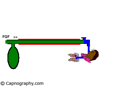 |
The expiratory valve close to face mask, separated by corrugated tube ( ) from reservoir bag and supply of fresh gases |
| Mapleson B |
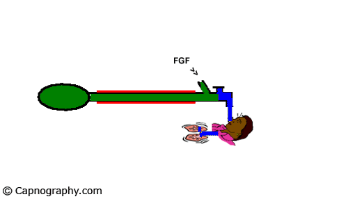 |
Expiratory valve and supply of fresh gases close to face mask, separated by corrugated tube ( ) from the reservoir bag |
| Mapleson C |
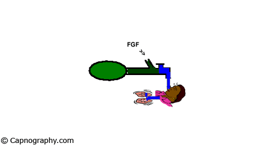 |
Expiratory valve, supply of fresh gases, and reservoir bag, all close to face mask (No corrugated tube ( ) |
| Mapleson D | 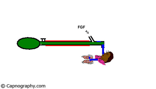 |
Supply of fresh gases close to face mask, separated by corrugated tube ( ) from reservoir bag and expiratory valve |
| Mapleson E | 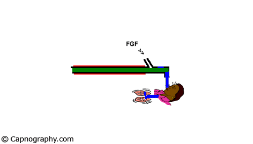 |
Supply of fresh gases close to a face mask. The open length of the corrugated tube ( ). No reservoir bag or expiratory valve. |
| Mapleson F | 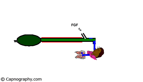 |
Supply of fresh gases close to the face mask. Corrugated tube ( ) present. . Reservoir bag with expiratory port but no expiratory valve.
Mapelson E with reservoir bag. |
Relative efficiency of rebreathing among various Mapleson circuits
| Spontaneous ventilation | A>DFE>CB |
| Controlled ventilation | DFE>BC> |
Mapleson A is most efficient during spontaneous ventilation. It is worst for controlled ventilation.
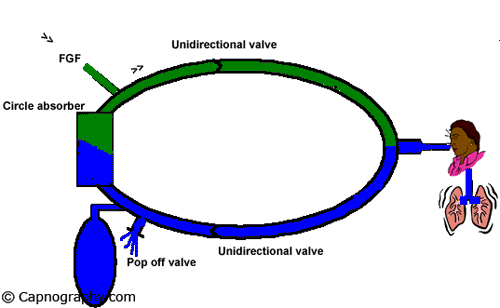
Circle system
Bain system
| This is a modified Mapleson D system, with fresh gas flow delivery tube running inside of the expiratory limb. |
 |
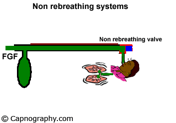
Non rebreathing system
| This is a unidirectional non rebreathing system with out CO2 absorption. A non rebreathing valve is located near the patient end. |
 |

 Twitter
 Youtube

